What Is a Shaft? Definition, Types, Materials, and Applications
Introduction
In mechanical engineering, a shaft is a rotating machine element that transmits torque and power from one component to another. Shafts are fundamental to power transmission systems across automotive, industrial, aerospace, marine, and robotics sectors. They provide the geometric backbone for precision components like gears, bearings, seals, couplings, and pulleys to function as an integrated drivetrain.
Beyond simply “spinning,” a shaft must satisfy multi-physics demands: torsional strength for torque, bending stiffness for dynamic alignment, fatigue life under cyclic loads, and dimensional stability across temperature and operating time. These demands vary drastically by application—from high-speed electric motors to heavy-duty off-highway gearboxes—so the design envelope is always application-specific.
Practical shaft engineering also requires tight coordination across disciplines: manufacturing (machinability, heat treatment, grinding allowances), quality (inspection datums, GD&T, traceability), and maintenance (lubrication pathways, corrosion protection, rebuild strategy). The most successful programs start with clear functional requirements and evolve designs that are both mechanically robust and production-ready.
What Is a Shaft?
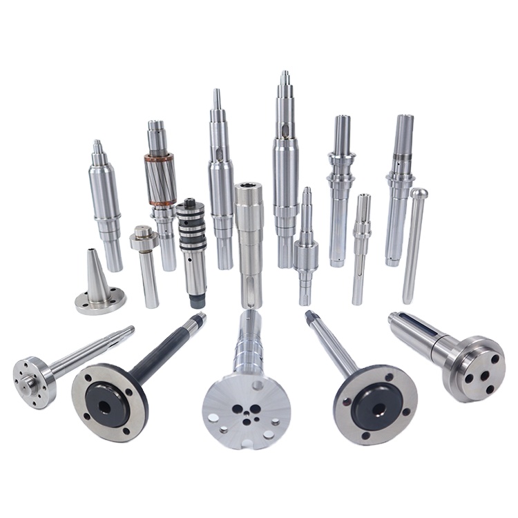
A shaft is typically a cylindrical component designed to carry rotating elements such as gears, pulleys, and couplings while transferring torque. Proper shaft design balances strength, stiffness, fatigue resistance, manufacturability, and cost. The outer geometry (diameters, fillets, shoulders) manages stress gradients and interfaces; the inner structure (material and microstructure) delivers strength, toughness, and durability.
Key functional features include bearing seats with concentricity control, gear seats with tightly controlled runout, keyways or splines for torque transfer, and threads or special ends for assembly. Critical transitions are filleted to mitigate stress concentration. Surface integrity—roughness, compressive residual stress, and coatings—directly impacts fatigue and tribology performance.
In modern practice, shaft development is an iterative process. Early concepts are validated via calculations and simulation (torsion/bending, critical speed, fatigue), followed by prototypes for metrology, balance, and endurance testing. Process capability (Cp/Cpk) and inspection planning ensure the production design is repeatable at scale.
Key design considerations:
- Load and torque requirements
- Material selection and heat treatment
- Surface finish and tolerances
- Straightness, runout, and balancing
- Keyways, splines, threads, and special ends
Common Shaft Types
Forged Shafts
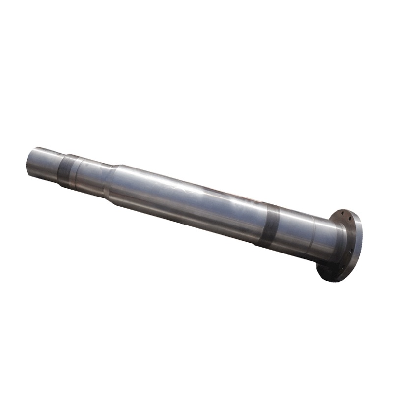
Forged shafts are formed by hot/cold forging for superior grain flow and strength, ideal for heavy-duty applications. The forging process consolidates material, closes porosity, and aligns grains along the load path, which improves fatigue resistance and impact toughness compared with purely machined bar stock.
Designers choose forging when the duty cycle involves shock loads, large bending moments, or long-life requirements under high stress. Hot-forged preforms are typically rough-turned, heat treated (Q&T, normalizing), then finish-ground on functional seats. Cold forging can further improve dimensional accuracy and introduce beneficial work hardening where appropriate.
Process control matters: billet chemistry and cleanliness, forging temperature windows, die lubrication, and post-forge heat treatment all drive microstructure and properties. Proper flash removal, de-scaling, and NDT (e.g., ultrasonic) are used for quality assurance, especially for large cross-sections.
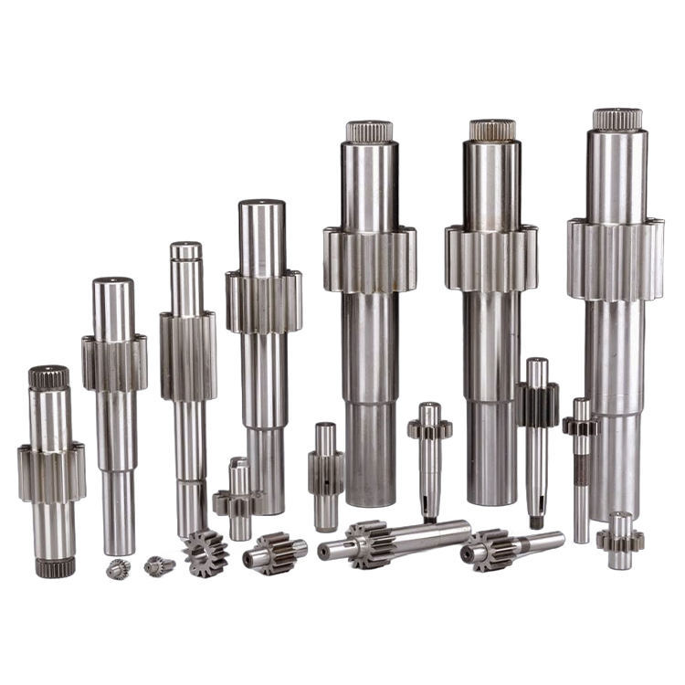
Gear Shafts
Gear shafts integrate gears and shaft bodies to transmit motion efficiently with precise tooth profiles. Integrated designs reduce assembly interfaces, minimize cumulative runout, and often improve NVH (noise, vibration, harshness) performance. Tooth profile accuracy (involute form, lead, pitch) is critical to load distribution and efficiency.
Manufacturing routes vary: rough-turning, heat treatment for core strength, semi-finishing, gear cutting (hobbing/shaping/grinding), and final seat grinding to lock concentric references. Where surface hardness is needed, carburizing or nitriding provides tooth wear resistance while preserving a tougher core.
For high-speed or high-torque applications, engineers evaluate contact stress, scuffing risk, and bending fatigue at tooth roots. Balance quality and straightness are controlled to prevent critical-speed issues. Robust filtration and lubrication design reduce wear and extend life in service.
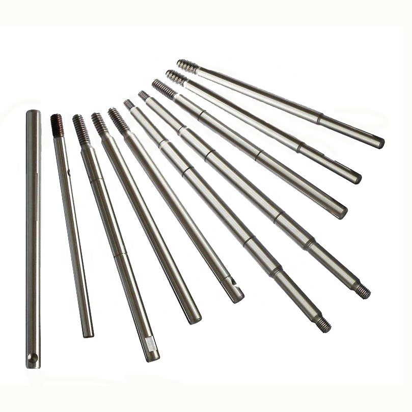
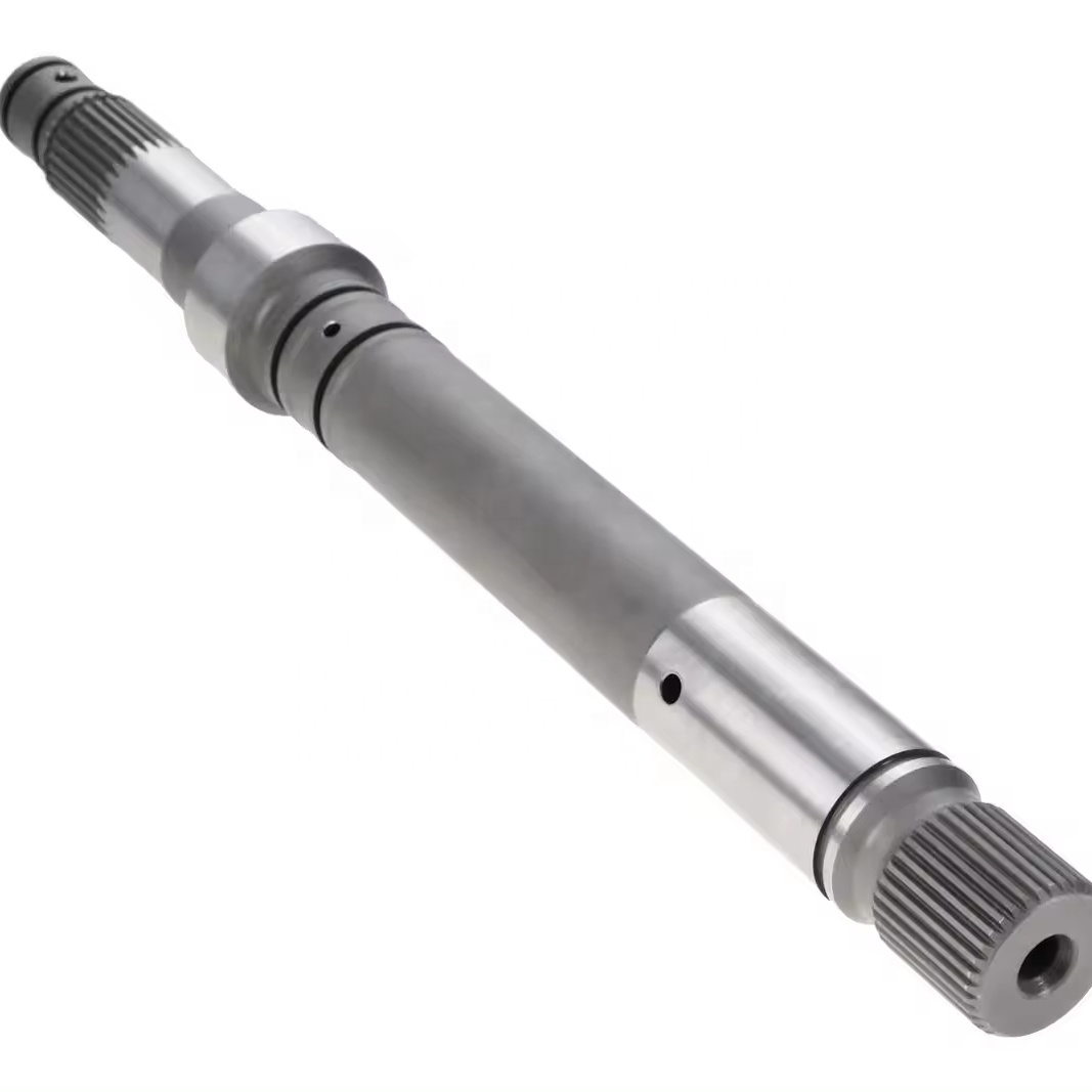
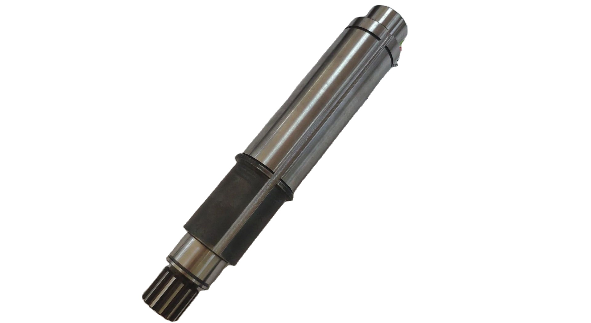
Motor Shafts
Motor shafts connect to electric motors and driven equipment, supporting features like keyways, threads, and custom ends. They must control runout, balance, and magnetic compatibility (for certain rotor designs). Shaft stiffness influences rotor dynamics, and surface finish on bearing seats directly affects bearing life.
Common features include tapered ends, shoulder steps for axial location, and anti-fretting measures at couplings. In traction and industrial drives, keyways or splines handle torque transfer; in compact appliances, press fits and adhesives may be preferred to save space and cost.
Thermal growth and corrosion resistance are also important—especially in humid or chemical environments. Stainless steels or coated surfaces mitigate corrosion, while proper fits and seal land finishes help maintain lubricant integrity and keep contaminants out.
Spline Shafts
Spline shafts feature longitudinal teeth that enable torque transfer with accurate axial positioning. Choices include involute, straight-sided, serrated, and helical splines—each with different load distribution and manufacturability characteristics. Proper fit classes (sliding vs. fixed) are essential to avoid fretting and backlash.
Manufacturing options include hobbing, shaping, broaching, rolling, or grinding, selected based on profile accuracy, throughput, and material hardness. Heat treatment (carburizing or nitriding) improves wear resistance, while grinding the major/minor diameters stabilizes fit quality.
Designers consider misalignment tolerance, lubrication pathways in sliding joints, and sealing. Analytical checks include spline shear stress, flank pressure, and torsional stiffness, combined with fatigue evaluations under combined torsion and bending.
Welded Shafts
Welded shafts join multiple components for complex assemblies and cost efficiency (e.g., friction or laser welding). This approach enables dissimilar materials (e.g., stainless to carbon steel), optimizes cost/performance, and creates geometries not feasible from a single piece.
Friction welding produces solid-state bonds with minimal heat-affected distortion; laser welding enables precise, low-heat input joints with excellent control. Post-weld straightening, stress relief, and finish machining are typically required to meet runout and fit tolerances.
Quality assurance includes macro/micro examination, hardness traverses, NDT (UT/RT/PT), and rotational balance checks. Well-controlled welding can achieve properties comparable to forged material at the joint, supporting demanding service conditions.
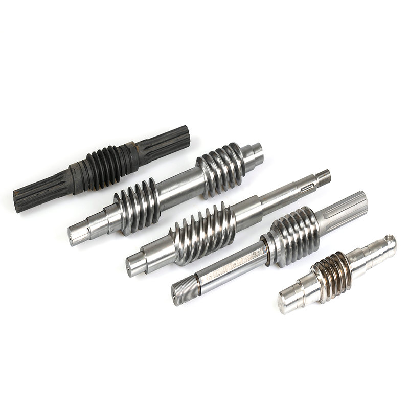
Worm Shafts
Worm shafts are threaded components that mesh with worm wheels to achieve compact, high-ratio reductions. They excel where right-angle layouts, self-locking, or high reduction in a single stage are desired. Precision thread geometry controls efficiency, noise, and backlash.
Key design variables include lead angle, number of starts, module, and material pairing (often hardened steel worm with bronze wheel). Proper lubrication (EP additives, adequate viscosity) and cooling prevent scuffing at sliding contacts.
Manufacturing may involve thread milling, hobbing, or thread grinding for accuracy. Heat treatment and surface finishing deliver the hardness and smoothness needed for efficient, quiet operation over long service lives.
Materials and Heat Treatment
Common materials: carbon steels (C45/1045), alloy steels (4140/4340), stainless steels (304/316/17-4PH), tool steels, aluminum, titanium, brass/bronze. Heat treatments include quenching & tempering, carburizing, nitriding, and induction hardening. Selection balances strength-toughness, hardenability, corrosion/temperature resistance, machinability, and cost.
For heavy-duty shafts, 42CrMo4/4140 offers an excellent strength-toughness balance. Stainless grades (e.g., 17-4PH) enable corrosion resistance with high strength. Carburizing yields hard wear-resistant surfaces over ductile cores—ideal for gear/spline regions—while nitriding provides hard cases with minimal distortion.
Process discipline is crucial: pre-heat-treatment stock allowance, quench media and agitation, tempering windows, and post-HT grinding all influence final dimensions and properties. When grinding hardened surfaces, burn-avoidance and residual-stress control protect fatigue performance.
Manufacturing Processes
- CNC turning & milling, deep-hole drilling for geometry creation and concentric references
- Precision grinding for tight tolerances and surface integrity on bearing/gear seats
- Spline cutting (hobbing/shaping/broaching) and gear cutting/grinding for profile accuracy
- Thread rolling or machining, keyway broaching or milling with radius management
- Heat treatment, straightening, and post-HT finishing to restore datums and runout
- Dynamic balancing, NDT, dimensional inspection (CMM), and documentation/traceability
Applications
Shafts are used in drive systems, transmissions, pumps, compressors, mixers, conveyors, robotics joints, and power generation equipment. In automotive, they enable e-axles, ICE powertrains, and steering systems. In aerospace, high-reliability shafts power actuation and accessory gearboxes. In marine and industrial plants, large shafts transmit power with strict vibration targets.
Trends include higher power density (demanding stronger materials and surface engineering), electrification (high-speed rotors and tighter balance), and smarter maintenance (condition monitoring for vibration, temperature, oil debris). These trends reward robust fundamentals and disciplined production.
Summary
A well-designed and precisely manufactured shaft ensures efficient, reliable power transmission. Selecting the right type, material, and process is key to performance and lifecycle cost. Teams that integrate design, manufacturing, and quality early routinely achieve better durability, lower NVH, and predictable delivery in production.
From forged to gear, motor, spline, welded, and worm shafts, each family rewards a specific set of design choices. Mastering those choices—geometry, microstructure, surface state, and process control—turns a simple cylinder into a high-performance drivetrain component.